i am interested in reproduced sound. but, i want something that approaches the texture and excitement of reality. not “clear”, “fat”, neutral (wtf!), “well damped”, compressed or “tight”. i see no advantage in the visual metaphors the audio press ignorantly leans upon for talking about sound. it has pushed sound designers in an awful direction. hearing is just as powerful as sight and harder to fool, these days. real is anything but those sounds. the sound of sitting in an audience is of course very different than sitting in your home… and the way things are recorded these days have much more to do with fantasy than reality. sitting at home can involve quite a bit of lovely fantasy, hopefully… but damping, compression and brightness are things that are added in (huge) amounts in the recording process currently. not really a part of my fantasy life. just the simple act of close miking a drum or a trumpet pisses me off now. it was fun for a change… but it’s all you get now. i gave completely up on mini monitors a long time ago for similar reasons. i like real! of course, i no longer live in a factory… in fact, i no longer live in the USA. and here in malmö, in möllevången, i live in an attic. there are loud neighbors and i have a 5 year old daughter. there ain’t going to be any horn speakers in my life. not for a while. so i have to compromise… but i choose to err on the side of texture, touch, and dynamics. the old “hard water” sound. the speaker thing is interesting. i’ll get to that. but today i want to talk about circuits, and how to best preserve the small substantial stuff that make things sound real.
direct coupled DC amplifiers are the least subtractive and, when done right, the least additive of all possible circuit approaches. by that i mean they lose things and add extra stuff you don’t want, the least. that is my opinion. it is based on 30 years of building all kinds of crap for many manufacturers and clients and for my own curiosity. what you want, or at least i do, is nothing but wire and tubes from input to output. i’ll accept a resistor or two, for stability or function, but it is an ideal to get rid of them too. sometimes you can’t and it’s better to have them than not…
anyway, no caps, no transformers… nada. but how is that possible? well, it is and it isn’t. yes, you can make an all dc otl line and power amp, and servo and safety the output… i have done a few simple ones. but i have ended up accepting the output trans in a power amp, at least for the time being. the isolation it provides is a bigger advantage than the disadvantage of the back emf of a speaker straight into the output impedance of an otl amp. don’t get me wrong. transformers kill off some of the fine detail and the low bass. they do. but the tricks you do to get the output impedance down low enough on an otl stage adds worse crap than what you end up losing with the trans… no free lunch. and caps? well, you still sometimes need them to isolate the power supply of one stage that shares power with another. i’d prefer not to, but how many power supplies do you want to build? caps in the supply seem to be necessary, but how necessary is a good question to ask all the time.
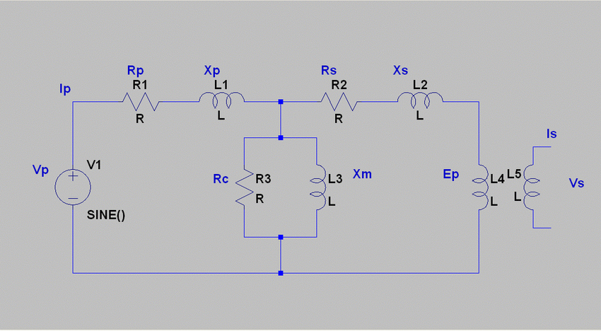
what’s wrong with caps? what’s wrong with transformers? nothing! the universe was incredibly generous to us when it wove together electricity and magnetism. but, in practice, and this is analog 101, the material science of these things is complex. caps are not simply caps, but a blend of resistors, inductors, other capacitors, a tiny rechargeable battery, a really tiny heater, a point contact diode, and a time machine. that goes quadruple for a transformer. many DIYers think that because there are only four wires, a single ended output transformer is “simple”. hahahhahahaahahahahahahahahahahaha! in your dreams, suckah! it’s interesting to look at the “simplified” equivalent circuit for a single ended transformer… “how did all those extra parts get in there?” this doesn’t include the lossy stuff or the parasitics. there is more L, some C and some weird spongy stuff you don’t want to know about. simple right? simple to solder in you mean… a transformer is NOT a simple device and adds a lot of electrical complexity. if you have a problem with this you don’t want to see the better more accurate model one uses to finesse. 4 wires my ass!
film capacitors have less issues than transformers, for sure, but there is still no free lunch. they store energy and then release it… but hang on to a little of it, then filter some of the surplus into whatever happens after a time, but not all… store some more the next trip, etc. and god forbid you block the thing in hard clipping into a fixed biased output stage. yowza! clipping performance is a big problem for cap coupling and represents a boundary. a boundary that transformers and dc coupling don’t share. caps have inductance too, a very small amount, but enough to radiate if the swing is big enough (which it is in a driver stage for a power triode). radiated emf is a pain in the ass wherever it is. even if it’s intentional. but especially when it radiates into the high impedance points of a circuit, especially if it creates a feedback path doing so. still, caps at those large AC voltages are pretty benign. especially in simple tube circuits. the place they really suck is at small signal levels. the reason is that the lossy stuff, the hysteresis, the leakage and the dielectric absorption are relatively fixed in magnitude… small. but if your signal is small they can be of close enough magnitude to be a problem. there is also some voltage variable character but it’s really small… unless the signal is small and the gain is large. preamps. ugh. i have given up on coupling caps in preamps. even teflon and polystyrene have a dull lossy sound that goes away as soon as they do. those are the GOOD caps! i used to rely on that to tone shit down. but at the end, they introduce more trouble than they solve. transformers actually do better at small signals. but they have many many issues, and some of the same issues as caps only in reverse.
transformers crap out at big swings of current or voltage. they add 3rd harmonic and ringing if they combine badly with other inductors… other basic problems are loss of fine detail, stray field pickup (they are antennas too), bandwidth limiting, and multiple pole filtering and varying phase shift. but most of all, one trans represents minimally a bandpass filter… if the poles of this coincide with other poles in the system, instability, ringing, distortion and delay are all added. this means you have to watch your poles with trannies… (you know who you are girls).
nope. best is to have none of that. but barring that (which is nearly always), best is to have the least possible of that.
so here is my dc for dummies.
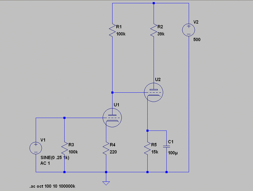
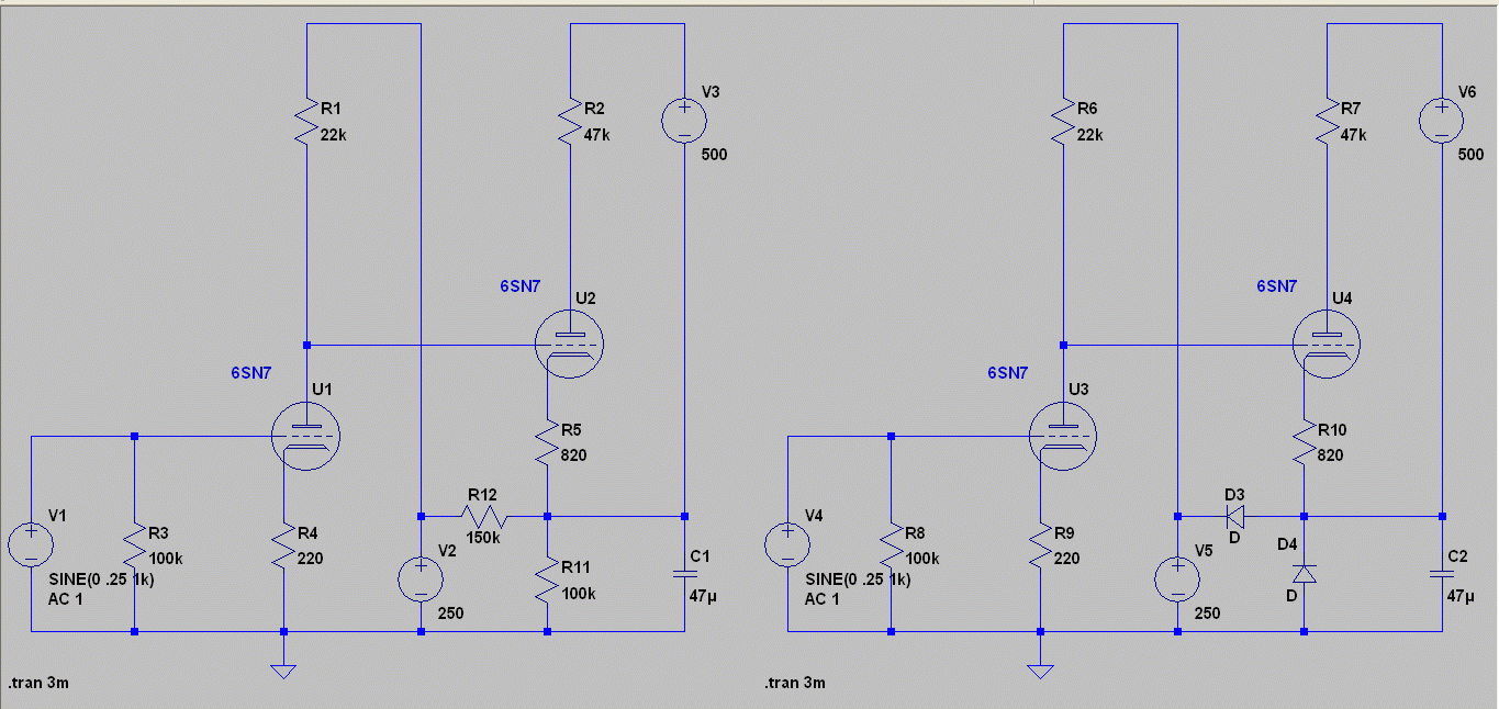
this is the basic most simple arrangement you see. the famous “loftin white” circuit is an improvement of this… but still basically this. the large bypassed cathode resistor sets the bias for the second stage and provides some DC feedback to adjust for small differences in characteristics over time. because the two stages share one supply and are out of phase with each other, any impedance in the supply provides negative voltage feedback back to the first stage and lowers distortion (a very small amount, but is stable). you must bypass R5 or the gain goes away. i have used a 6SN7 model to generate these values. one problem comes up right away… the operating points for the two stages really need to be thought about in order to optimize each stage for distortion and bandwidth. the miller capacitance will be high on the first stage as the gain is high and the bias of the second stage should be able to accomodate the swing of the first stage. with the minimum parts count in mind, these values are about as good as you can do, and they ain’t great. adding a few more parts can “optimize” the circuit in this regard. reducing the gain on the first stage increases the overall bandwidth by reducing the miller in. the lower gain improves the headroom between the two stages and you can let the second stage rip…
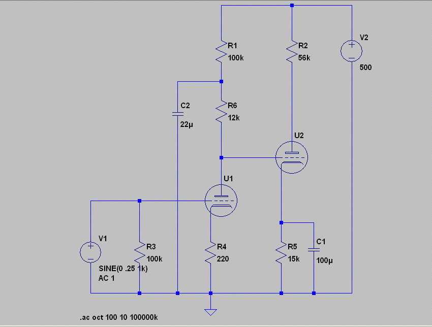
adding one decoupling cap and splitting the plate resistor of the first stage shows how the addition of just 2 parts can cut the distortion in half and improve the -3dB at high frequencies. this is in no way meant to be definitive… just shown to give you the basic ideas.
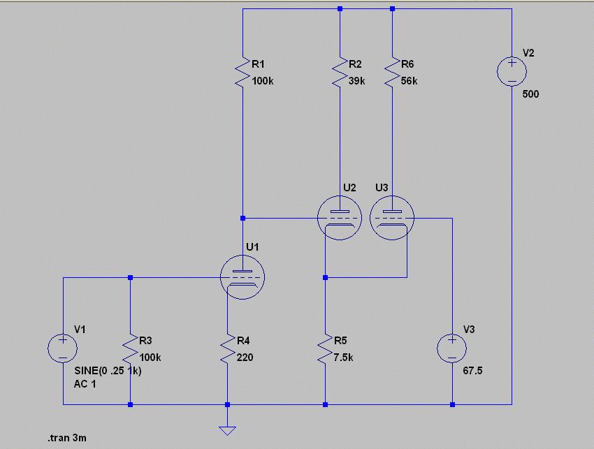
if the caps really bother you, and there is good reason to get rid of as many of them as possible, you can add another tube in the second stage and forgo the bypass. you don’t have to use the output from the second half of the second stage (although it certainly can come in handy). please note that the plate resistors will not be equal if you are after equal gain from them… equal current can be had by controlling the grid of U3. that’s a really useful circuit, that. but there is more freedom to be had sometimes, by not having to rely on one power supply.
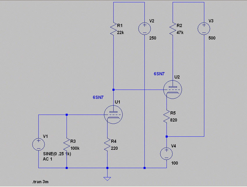
it is crazy how simple the coupling can become when you add a lot of extra power supplies… this pic is meant to demonstrate the idea… there are many finesses to doing this. one very simple and useful one is to tie the bias point of the second stage to the first, like so:
some of you will recognise this as the underlying idea behind the “dinosaur 50” amp, from sound practices many years ago.
i will post more here soon….
