it’s been awhile. a tough bunch a months.
at the time of writing this there’s an election looming, in the usa, that will set the course of the next generation and it’s economic future. there’s “frankenstorm” on the american east coast and an earthquake and tsunami on the west: all matter of unnatural and natural catastrophe. in the usa, very few seem to realize there are just a few small mistakes left between generally crappy and a major meltdown. that this was caused by the former republican president and his advisors has been both completely forgotten and successfully made vague. “it’s the black guy’s fault”. the de-distribution of american wealth that began under bush’s watch has continued helter skelter. never in the history of personal wealth have the wealthy been so rich and in my opinion, so undeserving of it. many of them make nothing. they speculate, gamble, con or just plain steal. like goldman sachs. like morgan stanley. like citigroup. like bain. on the flipside, poverty is now almost mainstream. it is crazy, to me, no one seems to care how this happened. most just want a slice off the flank. it’s business as usual. those responsible for informing the public have been downsized, both teachers and journalists. propagandists have replaced them, and are actually much more profitable. conspiracy theories, the price of gas and who gets to boss the vagina around gets more attention than why it’s that way in the first place. the mainstream media’s open racism and radical revisionism of all history, and even of science, has tainted the process to the point where it is actually hard to find out what the fuck IS going on. you have to watch the fake news to make any sense of it (thank goodness for john stewart and stephen colbert). comedians, like chris rock, make fake public service announcements that are way more honest and useful than any political organization. it should be funny…
hanging over the american election: corporate money has utterly corrupted the democratic process. if romney wins, he will have proved that elections can be bought in the usa.
and things are hard everywhere! the storm that trashed the east coast just now, trashed the caribbean before that. there’s no electricity or safe place to sleep, or sanitary way to take a shit, or a shower… for lots of people there. the eu’s money problems persist and inequality there threatens to split the union. the arab spring has collapsed. syria, jordan and lebanon are primed to blow together! beyond the false pride, economics and human costs of the wars we just can’t seem to “win”, corporate greed and avarice have become status values. the answer. things to take comfort in. “at least our billionaires are richer than yours”, “we” must be doing something right? this is how we do business. god bless.
it feels a little odd and even a bit shameful to be thinking about circuit hacking under the circumstances… about art and craft. about making weird machines. although it is a nice place to escape to. i have friends who have no lights, heat or water at the moment. it’s getting cold and there’s a nor-easter on it’s way to nyc. i guess i want to say that i feel compassion, sadness, and anxiety for the people over there. i am grateful i have a job and a roof over my family’s head.
i want to go back to a discussion of current amplifiers and also of current feedback. i’m a little rusty at the blog thing…. this will be a good way to ease back into it.
the ee universe is a man’s world, sadly. yes, and a man worthy of the name, pays attention to the volts. you think i’m joking?! i am simply stating a fact. ours is a voltage-centric discipline. a “thevenized” kind of bag. thevenin is the ralph cramden of engineering attitudes, and there is nothing more conventional and everyman than that. CAD relies heavily upon it too, as nearly all equivalent circuit simplification starts there. if you are not sure of what i am talking about, please go look it up. it is worth your time and will help you in your work. i am simply going to the punch line because i need to get some where else, but i want you to know why. because of thevenin, we tend to analyze active devices in his terms. an ideal voltage amplifier is a voltage source with an output impedance of 0 ohms. a short circuit. and it likes to work UP, into it’s load, which has some finite value.
as with everything else under the sun, there is another side of the tracks… and it is called norton. the bald headed goofy well-meaning idiot-savant. emphasis on savant. well educated EEs will of course point out, and rightfully so, that in the end, thevenin and norton are simply flipsides of the same insight: that no matter what kind of electrical circuit you have, it can be simplified into one relationship between volts, current and impedance right where the source of power meets the circuit. they come to the same conclusion. one pushes a bus and the other works in the sewer. yes yes… well said.
i say, there is a practical limit there which tends to be pushed aside in our haste to get to the end of the job well done. there isn’t a practical amplifying device made today that is a short circuit or reliably drives one.
on the other hand, norton has a different perspective of these things. the current-centric view. and a current source can be viewed, ala` norton, as an infinite impedance looking DOWN into a finite load. so what? as noted, you wind up with the same result. the big difference is that all of the practical devices we have to work with today are much more reliable, or how about “happier”, as open circuits than they are as shorts. vacuum tubes in particular, and especially tetrodes/pentodes, could be said to fit this view very nicely.
voltage feedback and current feedback have some related twists relating to thevenin and norton practically, but as my perspective is controversial, i am going to save most of that for another day. it is uncontroversial to say that voltage feedback and current feedback transform practical amplifiers in slightly different ways. there can be advantages to current feedback in the way it handles impedance transformation… even though in the end you have the “same” result.
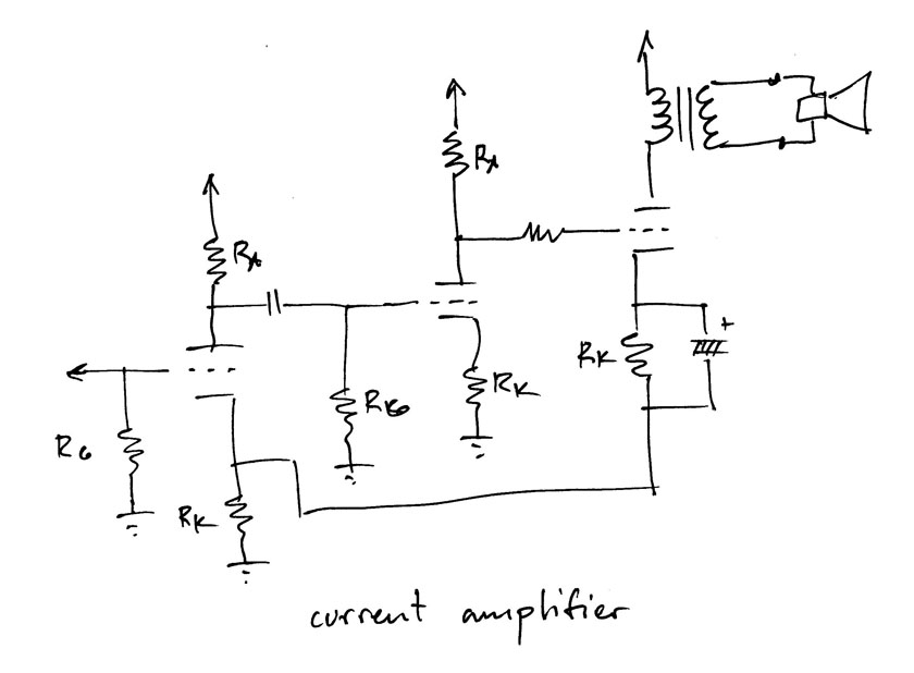
below is a simple example of one of the most basic ways to return negative current feedback to the first stage. most modern voltage feedback op amps are actually based on this exact arrangement. the main difference is that this is half of the circuit. the op amp would have a differential input. but in this case, the “input” for the feedback circuit is low impedance… the cathode. the input for the signal is very high impedance, the grid. i think this is accurately describes a current feedback amplifier. i also believe modern current feedback op amps are different in that they respond to current at the inverting input. but that shouldn’t change this discussion. we’ll see who yells at me for all this…
here, you see two grounded cathode inverting gain stages, plus a cathode follower buffer, which returns it’s current variations (the swing through it’s Rk) back to the cathode resistor of the first stage. these current variations are in opposite phase to those in the first stage. consider what happens when the cathode follower has to dump extra current into a load…. loading it down. there is less current variation in Rk. less CFB. more voltage into the buffer. this tends to stabilize the output. this is classic negative feedback error correction, done with current. one fabulous feature is that the error signal is DC coupled.
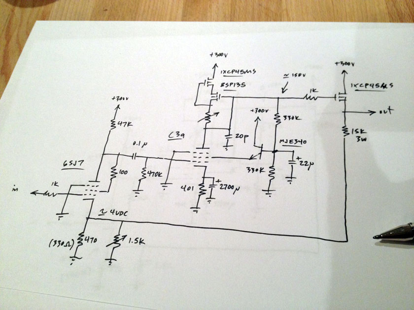
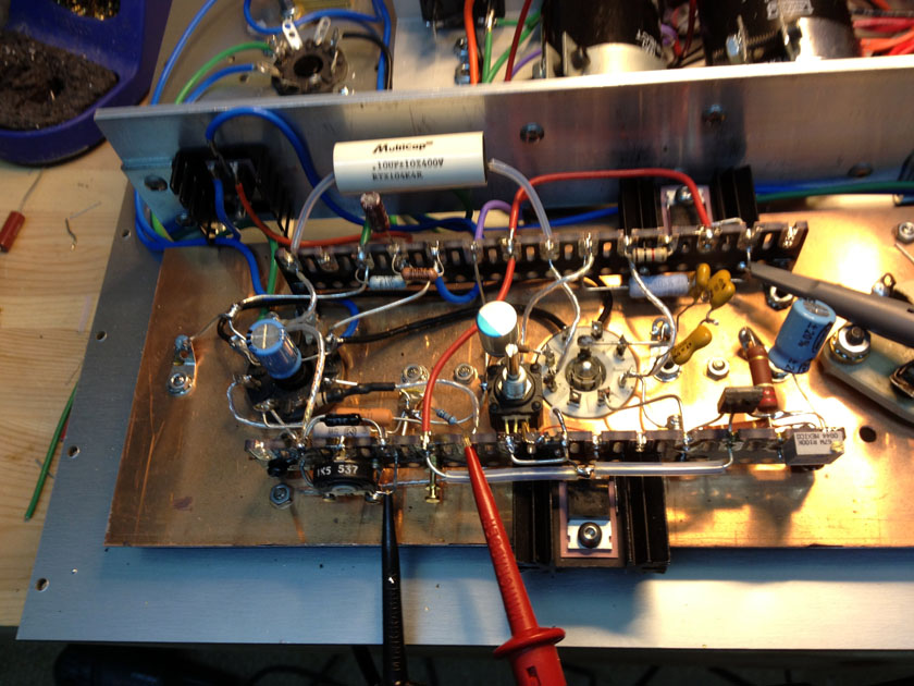
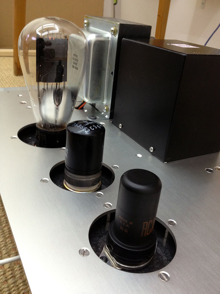
above is a very fancy practical hybrid version with metal pentodes and extraordinary performance. the 6SJ7 (triode wired) is set for a gain of 24 dB. and the C3g is a Gm amp, with a gain of 65 dB. that is roughly 90 dB of gain for the two. the bandwidth is DC to -3 dB at 18KHz open loop. the buffer is a depletion mode mosfet with 10mA going though it. that is probably not enough but it is what i have in the supply. there are better parts for this job… yes, this combination is sure to piss off a few! of course that’s why i do it. i will wire up a version with submini tubes (solder leads) under the hood for comparison. here, i have dialed in 58dB of current feedback for a closed loop gain of 32 dB. the 20pF compensation cap is for stability. below is a view of the prototype. the heatsinks are for the current source and buffer mosfets.
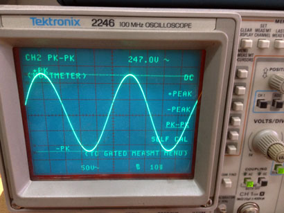
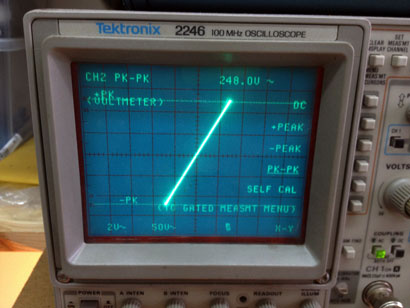
 here are some measurements for you. first is a 250 Vpp sine wave at 20KHz. it looks like a sine wave but nice and big. 50 volts per centimeter. the next image is much more impressive. it is an X/Y measurement of the same signal. note the simple straight line. it is completely closed. without a distortion analyzer or phase meter i can still say that this 250 Vpp is provided with well under 1% distortion, and well under 1 degree of phase shift. probably under 0.1% and 0.5 degrees.
that this was accomplished with 5 active devices is pretty cool. the two gain stages are tubed. it could be all tube, but that would put a bunch more holes on the top panel, and there isn’t any real advantage. the current source and the buffer don’t have to be tubes. also, to do this in only solid state is not that easy. most of the practical devices available have too much input capacitance (and the C is too voltage variable) and the high voltage would cause problems. you could go to more devices and get to the same place where this design is… cascode high voltage transistors, or mosfets. but there would be a great deal more phase shift at 20KHz with any 2 high voltage transistors and the same mosfets. the tubes i use here have very low input C and and are voltage controlled.
most tube circuits aren’t expected to work this well. especially in the DIY world. but also in the “high end” world… of course, there will be many who immediately ask, “but, how does it sound?”. “feedback! what the fuck!” “who needs it to be that good!” and, “it ain’t natural” (for some reason i hear jeffrey jackson saying this to me…). look, electronics is the antithesis of natural. i say, it all depends on what you use it for… i plan to drive some big globe 50 tubes with it. i’m pretty happy about it. i’ll have more to say about this… later.
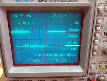
the square wave pic simply shows that the X/Y plot is very real. it is boring in it’s simplicity. no ringing, no rounded edges… it’s just a plain old 1 KHz square wave. 22 Vpp with half a volt in.
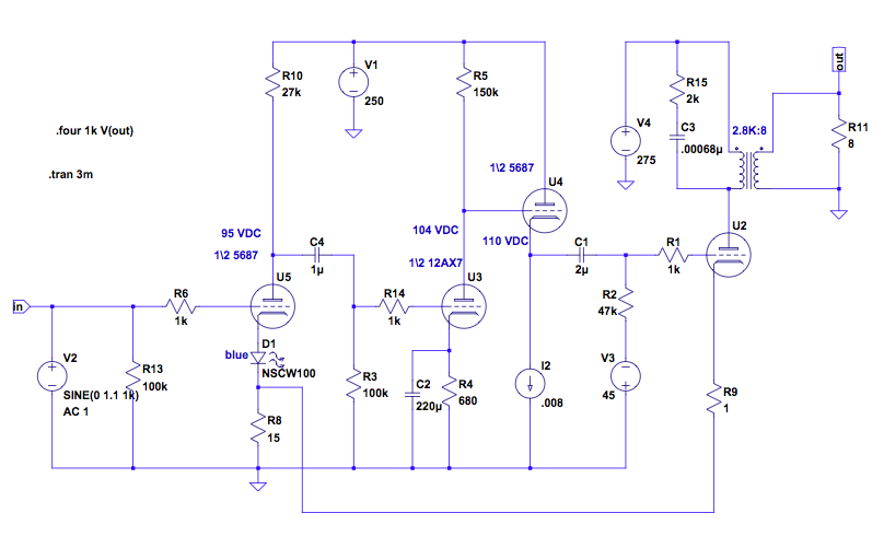
now for an interesting variation, imagine making the 3rd stage a transformer coupled grounded cathode stage… but what about the phase? it is an inverting stage at the plate but the current variations through the tube are the same as for the cathode follower. it is still negative cfb returned to the first stage. but in this case, the output impedance at the plate will be increased. the unbypassed resistance of the first stage’s Rk (which is in series with the output stage’s Rk), times the gain against the error signal there. variations in load impedance will have the opposite behavior of the typical voltage amp. with the source impedance (the amp) higher than the load’s, the output current will tend to be regulated by the feedback, and the voltage will track the impedance.
now why would that be cool?
well, imagine you are interested in driving a “full range” speaker (a misnomer) or a compression driver connected to a horn. both of these speakers have difficulties at the bottom (near resonance) and at the top (roll off from the mass of the piston). a traditional voltage feedback power amp (with an “infinitely” low source impedance) would have a good “damping factor” and would dump more current into the load as it approached 0 ohms, and less as it increased. it would have to do this in order to keep the output voltage “regulated” as compared to the input signal. but, this would result in a loss of bass and treble into both “full range” speakers and compression drivers, as the impedance is rising at both of these frequencies… and the efficiency is fading at the low frequency end, at the same time. a current amplifier, with it’s higher source impedance, would look at these particular loads quite differently. the output voltage would track the impedance of the speaker. and you would have extension of both the bass and the treble.
this is interesting for me as i use manger drivers in my system. mangers are complicated drivers. they are bending wave drivers above 400 Hz, really inefficient piston drivers below, and beamy laser beams above 1 KHz. i have a love/hate thing with them, for sure. but they do one thing better than all standard moving coil dynamic drivers: their impulse response is almost perfectly in time with the drive signal. if you can cross them over to a bass driver low enough, and keep the woofer output out of the midrange as much as possible, and then deal with the beaminess… (i have gone the way of the diffusor), you have something pretty special. at least for a small to mid sized room. they do make excellent monitors for recording as there is no appreciable group delay or phase shift over the range of 150 to 30KHz (!). they can reproduce a square wave. the number of speakers ever made that can, can be counted on one hand.
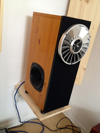
 if i could get a bit more extension at the low end of the manger, it would help me with the crossover to the woofer… i want as little woofer output as possible mixed in with the manger. so i put the woofers on the sides of the baffle, with an electronic crossover (18dB/octave). this will be steeper in practice with the mechanical crossover of the baffle added in… also, i can use the back wall as a boundary reinforcement, to get a boost in the very low frequencies. this allows use of smaller woofers (2 of them). but the fact is the manger starts to crap out at 400 Hz. and X max is 2mm. they are easy to blow up, and crazy expensive. we have had a great deal of experience with them at silbatone.
so, back to the current amplifier. i have made one using an 807 beam tetrode. it drives the manger safely to 100 Hz, and drops off. at the top, i get a 3dB rise in output up around 9KHz with the amp, which flattens out when the diffusor is installed. it’s a touch dull with the regular amps. i’ve been listening to it full range for a few months now and it is wonderful. a good mix of compromises. the diffusor was designed by MJ Chung. it works very nicely. no more laser beam.
but this isn’t the only thing i am working on… i think the most useful place to use a current amp is on compression drivers. the big advantage now shifts to the high frequency end of things… because of mass roll off, many compression drivers, especially older ones, are limited to a fundamental range of about 6 to 12 KHz. think of a WE555 or an altec 288. modern drivers have wacky tricks to extend the range by use of resonance and peaking. it has never impressed me as a sound approach. the classic approach was equalizing the driver and using a super tweeter. a current amp offers a middle way. the output rises with impedance. the amp equalizes the output. it is very natural and not anywhere as harsh as what you get with the modern beryllium peaking types. i have only heard this on a an altec 288A. but plan to test out some things soon on the WE555 and WE594. more on that, later. the real interest for me is with full range horns. and drivers like the WE555. the vitavox low resonance freq. compression drivers are also very interesting to me.
obviously, if you are into “full range” drivers, current amps are something to check out. by the way, nelson pass has been into this for some time. way longer than me. he has a bunch of really interesting stuff on his website along these lines. i do have to control my gag reflex when it comes to lowthers, but many people like them. a current amp could (nothing can save those pieces of shit) help…?
here is the 807 current amp design adapted for 2A3s. i have substituted more common tubes than i used. i can recommend the 2A3 EH (made in russia), but 6B4Gs or any of the extended family would do… or even a 6AV5 or 6550 could be crowbarred in there. i used one electron output trannies for this test and they didn’t disappoint. you can use whatever you can get… fun, and interesting.
addendum!
after a great deal of trouble driving the output stage with the current feedback driver stage shown above, i had to back up and get some help… 2 quick conversations with morgan jones and frank blöhbaum (at etf) helped enormously. i blew up a bunch of fancy depletion mode mos, and normal run of the mill hexfet enhancement mode mosfets too. it was hard to see what the failure mechanism was (morgan was extolling the virtues of inexpensive digital oscilloscopes for the ability to record events… i guess now i have one on my christmas wish list). it eventually turned out to be the gate charge and the extremely high impedance of the gM amp (the C3g stage). you learn something new every day. i had diodes and up to 5k gate stopper. boom. especially on big transients. i ended up using an IRF730 with a 10k gate stopper (!), a 12 volt zener from gate to source, and a 100 ohm source resistor in order to make it reliable. but the performance is affected. the much lower C in of the IXCP45MS allowed a large amount of current feedback (58 dB) with relatively modest compensation. the much larger value of input C on a hexfet changed everything. it was much harder to manage it without oscillation. i ended up increasing the compensation cap to 420pF! it had been 20p. and it is still just stable at clipping… i will work on making the fancy mos more reliable. while this measures and sounds excellent, it can be better. it makes me appreciate tubes all the more.
i switched to a submini tube as a cathode follower (because a solder lead tube fit under the chassis and i didn’t need to drill any more holes) and everything was perfectly stable with much less compensation. it is so easy to compensate tubes, at least if you know them… but the insertion loss was 50 volts! the mos dropped 5. my 250 volts of swing became 200 just like that. tubes just don’t have the transconductance to make really good simple buffers. they need help. they sound good, don’t get me wrong, but solid state does buffers without losing so much level. at line level, who cares. but for lots of volts, they eat up swing.
so back to the mosfets. i have been compensating the driver stage by using a shunt cap to ground from the C3g plate. this is supposed to help define the pole associated with this stage and prevent it from screwing with the other poles… particularly the buffer and opt tube. i have switched to using a “miller” compensation scheme (basically the cap goes from plate to grid) instead and everything works much better… why throw bandwidth away for stability without getting anything for it? miller effect is negative feedback. you get the compensation needed AND distortion is reduced in the attenuation band. now, even the fancy depletion mos is stable and i don’t need more than 22p of C.
i meant to drive a 50 tube and test something i have wanted to for years. 50’s are tough to drive because they have a largely variable input admittance. for this reason, they expressly do not recommend fixed bias and most of the amps you will ever find that used them were transformer coupled to the grid (low impedance) and self-biased. the grid current varies from negative to positive quite a bit from cutoff to saturation. with fixed bias, there is nothing to prevent runaway if the bias shifts due to clipping or asymmetrical waveforms of large amplitude (drums and synth pulses from dance music…). i want to push the envelope and see what i can get away with. the problem is the resistor connecting the 50 grid to the source of bias: for cap coupling, this is usually on the order of 100k to 500k. this allows a cap of reasonable size to be used, typically .047uF to .47uF, for low frequency performance. this maximum requirement is always reduced for fixed bias… an EL34 in fixed bias shouldn’t have it’s Rg exceed 50K. most amp manufacturers have no clue. this is a major source of failure in the musical instrument amp business. a 50k grid resistor would need a minimum of 1uF and probably more like 2uF for anything quality in an RC coupled fixed bias amp, if you wanted a reasonable low frequency performance. that is a big and expensive part.
i have always got around it by direct coupling. no cap is the best cap. but i wanted to know just what the range was… and my contrary nature began to tug at me: who says it can’t be done! so i want to make a reliable cap coupled fixed biased 50 amp. driven with metal pentodes and very high performance. fixed bias gives a bit more power. when you are talking about a 4 watt amp, an extra watt doesn’t hurt.
so here it is. after a bunch of head scratching, it works fine. not only is it fixed bias, but cap coupled. it sounds fabulous as it should… it makes just under 6 watts at 2% thd. almost 1 and a half more watts. i even tested an electrolytic coupling cap (4.7uF 400V, bypassed with a silver mica .001) and it still sounds and tests excellent. look, i just can’t help it… tell me i can’t or shouldn’t and i just have to try. panasonic won again, by the way, over sprague and illinois. but now i am using a 2uF film and foil. i worry about such big AC swings across an electrolytic… if it weren’t such a rare output tube, i would let it rip. the grid resistor is 12K. i started out with 5k (and the 4.7uF electrolytic). the drop across the resistor at clipping is 0.4 volts… not enough to worry about. at 50k, this would be 3 volts less bias. 100K would be 5 or 6. you see the problem. the grid current and the voltage drop across the grid resistor would destroy the tube.
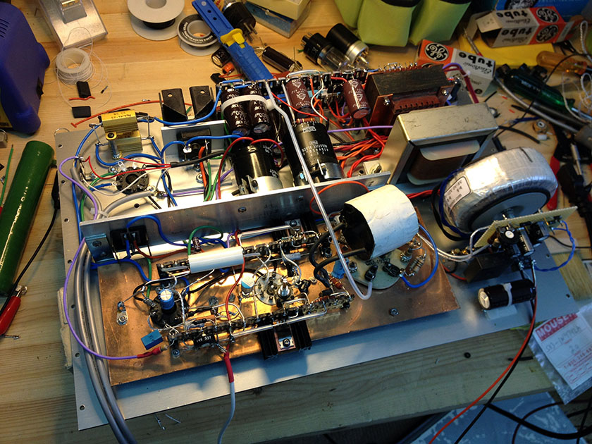 and finally, here is a look at the top. now i have to make the other channel… bleh! i need an intern. more soon…


