it’s 2021. do you know where your mind is?
my molecules are so spread out, any farther apart and they will disassociate. surface tension isn’t helping. work force is low… no amount of attraction seems to be enough to keep “me” in one piece. so i have decided to let go, and just let it all hang out. it’s like in that anime series, “転生したらスライムだった件”, or “that time i was reincarnated as a slime”, where the main character awakes to find himself transformed into a gelatinous blob, like Kafka’s roach. and has to cope. it all works out in that story! i should take heart.
today its time to go inwards a bit, not to the molecular level, but… to take a little deeper look at the components. to assist in this i am turning to the making of measurements. and i want in particular to look at the oscilloscope, the AC voltmeter and the curve tracer. the curve tracer, i admit, is a bit of luxury kit. no one really needs one. not actually… the best tube tester in the world is the equipment the tubes are going into. but they sure are amazing at illustrating some deeper reality! and for looking at what is going on at the corners and edges, a tracer is nothing short of incredible.
i have designed and built many gadgets for testing and measuring tubes. it was actually my job at one point. i designed and built a pair of automatic tube testers together with Mike Abram, who has since passed, and the tech crew for New Sensor Corp (Electro Harmonix). those two machines tested 8 million tubes before i left in 2008. and those machines reduced the return rate for all tubes to 2% during the time i worked there. i know for a fact i earned my paycheck. tube testing is important at the manufacturing end, and also at the highly diagnostic end. but they are used much more commonly for marketing: for the selling of tubes. which, is something i find deeply problematic… but am powerless to do anything about! in any case, while i have used the tektronix curve tracers in the past (both the tube only and the solid state for either), and even a quan tech (!) noise measurement system with an X/Y scope, once or twice, i have never made a tracer… i never needed one, because it doesn’t actually help one make things. you still have to work with what you can get! and i am a fan of working with what you have. so many engineers i have met, and DIY people, impose answers onto their designs, instead of listening to what the design has to say on it’s own. they all have a story to tell, if we only listen to it.
after the last four years, most of us have got to be sick and tired of living with weird fantasy! i am! in any case, as i have mentioned before, i own and love an “etracer”. designed and made by Chris Chang, it brings high end curve tracing into your shack, for a crazy fair price. and for that i have no problem giving it a plug. or plugging it in.

above is a curve trace of one of my fave tubes: the 6688. this is a 6688B… but they also come as E180F, 6J11P (russian) and there are other equivalents. do your own research! there are many angles on finding some! there are also many other VHF pentodes with the same pinout, so making designs using this tube is sensible because there will probably be some kind of tube that will plug in and work in your shit, for a long time to come. this is a good part to build your own stuff with because it isn’t used in any commercial audio equipment, except for special cases in asia. so you aren’t competing with audiophiles for parts. that is a great thing! GE made lots of 6688s because they were common in military VHF communications gear, and radar. so there are still stocks of them around. maybe not for long, now?
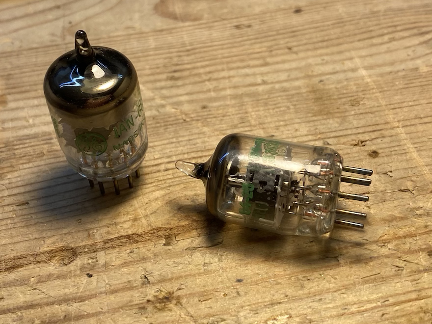
there is much to recommend VHF pentodes like this. they have a frame grid… low microphony, high transconductance, low capacitance, even triode wired they are marvelous, linear and long lived (the “SQ” versions are 10,000 hour tubes). and another reason they are still inexpensive, is because they are VHF pentodes and not big attractive “audio identifying” octal base tubes from the 40’s and 50’s. no, they have 0 audio market glamour. however, they make up for their lack of glamour with major fabulosity in performance… there are very few pre frame grid tubes that can compete in QUALITY of performance. so if you don’t absolutely need to look at the tubes, you get a lot back in terms of good sound!
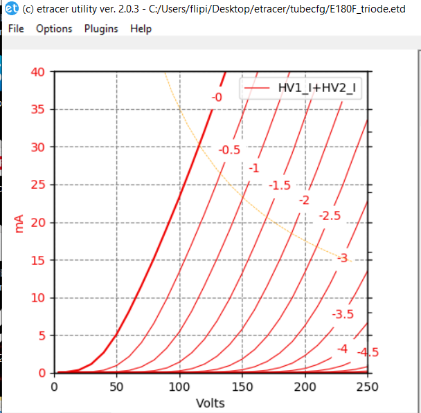
above you see the exact same tube in triode operation (screen tied to the plate, and supressor tied to the cathode). for the best noise performance you always want to bypass the suppressor grid with a cap, just so you know. you don’t have to, but to go the extra mile…
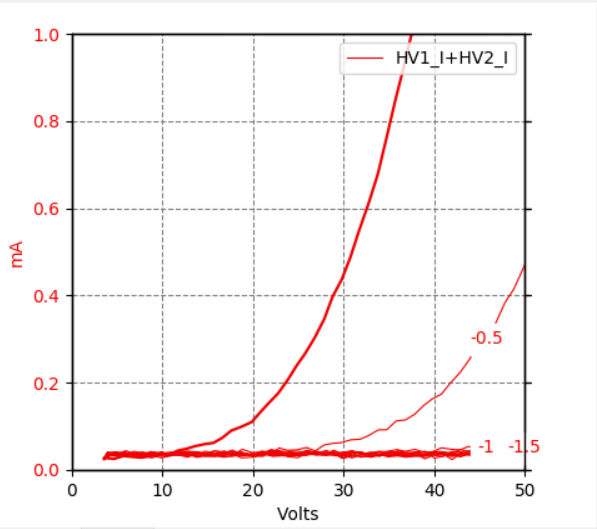
it should be clear that the actual tube under test, above, is a marvel and seemingly in perfect operating order. but lets look at the details a bit closer. the etracer has some limitations at the very small scale. it wasn’t made to do this! you can’t zoom in on less than 50 plate volts and the first few volts are not really there with enough detail. but you can still see a lot that isn’t in the tube manual!
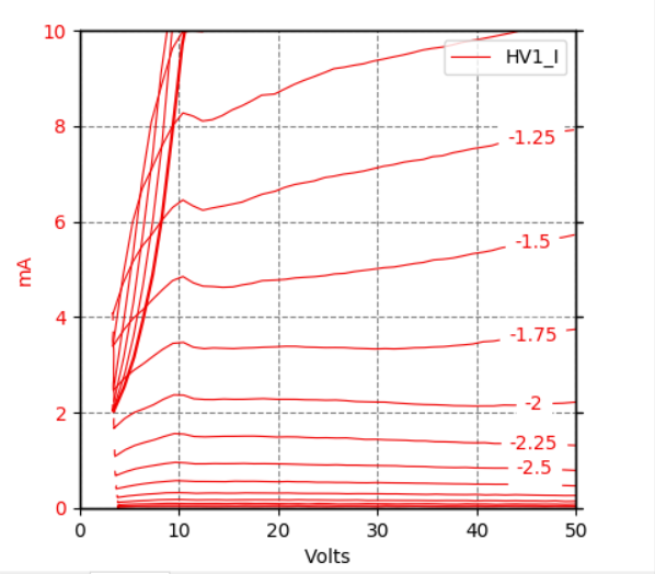
in the bottom left hand corner, where the plate volts are low but the grid bias and screen voltage are fixed. there are some interesting things going on. one of the obvious features of this part of the 6688’s characteristics, is the way it turns “ON”. you can see the “triode” part of the pentode characteristics. it would be interesting to pull that apart a bit better, like the first 10 or 12 plate volts. but again, this is not a Tektronix or an HP curve tracer. it is purpose built to test tubes in a useful way. it’s very affordable! and it’s very accurate! but it’s good to see the “triode” curves down in there… they should be there! and they happen pretty much between the diode line (0 volts bias) and -0.6 volts bias. and they look… reversed!? hmmmm….
another interesting feature is that little dive in plate current between 10 and 20 plate volts… what’s that all about? that is a very interesting feature! at low plate volts, the suppressor grid fails to prevent secondary emission from the plate making it’s way back to the screen. this dip is called “the negative resistance region”. it is short lived in this tube, because of the suppressor grid. but between 10 and 15 plate volts, the suppressor grid doesn’t work unless the tube is functioning as a… triode! which you can see the in transition between the two modes at around -0.75 grid Volts and 10 plate Volts. ordinary tetrodes, not “beam tetrodes” have much more of this dip. enough to be of use! but it’s good to see it here… we know this is a real tube and not some fake ass ideal.
that’s good intel.
also very interesting is the “constant current region”. note that from -1.75 volts, going more negative, the plate characteristic ceases to follow ohms law at all. regardless of plate volts, the current is basically an open circuit, from 10 volts to off to the left somewhere: 250 plate volts. -2.75 volts makes an impressive 0.5 mA current source or sink. the impedance there would be many 10’s of megohms.
below you see the same region but in “triode mode”. here you see an extremely variable mu. this is the tale of “the triode comes to life”. it isn’t a clean or simple transition from “OFF” to “ON”. the diode line looks to have a mu of something like 30… once it gets going. but at -0.5 volts it looks nearly double! maybe as much as 60. and -1 has got to be over 100,but the current is well under 100uA. you can see my curve tracer needs to be calibrated again… that mass of red lines should be firmly planted on 0 mA! oh joy! more maintenance to do! for this discussion, though, the trend is what matters.
and maybe more useful is to look at the entire region from 0 to 250 plate volts?
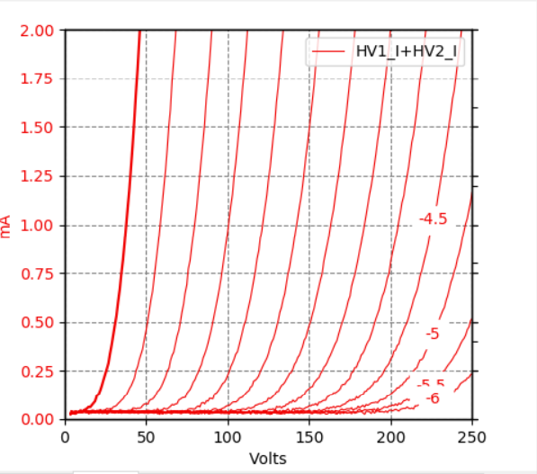
clearly, as the measurements reveal, as one increases plate voltage AND bias, there is a gentle shift to the right in the curves. this is an indication of an subtle increase in mu and plate resistance, and a decrease in transconductance. we expect to see that and there it is. also, by the time we get over to the right of the curves, we have a variable mu, and a continual non-linear transition from off to on. triodes are not particularly “sharp cutoff”, are they? under a quarter mA, it is still very interesting!
but one additional look above tells quite a lovely story too…. loading this tube with a constant current source would make a GREAT DEAL of SENSE! a horizontal loadline straight across 2 mA, or 1 mA, is insanely linear. it’s like a ruler! remember this is an actual measurement… it isn’t some ideal graph in a book. if maximum swing was what you were after, a plate voltage of 140 volts, and a 1 mA current regulator as a load could get you an almost perfect 220 volts pp with 5 volts pp input signal. yes it would be high impedance, but with a big swing buffer, that might be all she wrote! 220pp/5pp = 44. at this low current, with a high Z load, mu is high too. at higher plate currents, mu goes down. and a resistor load will get you barely to 36. also remember that as you go up in plate current, you get less headroom against maximum dissipation. so staying down low can give you that too… again, good intel!
okay, that was fun. but what does it mean? it doesn’t mean shit! not until the rubber meets the road! so lets make something!
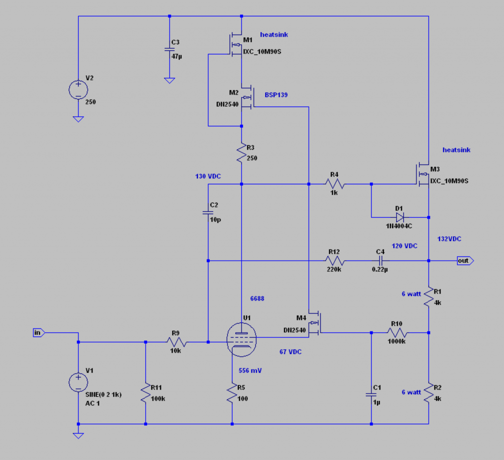
above you see a typical (for me) pentode transconductance amplifier circuit with a depletion MOSFET buffer and negative feedback from the buffer out to the grid at the input. with 220K back to 10K we get should get a closed loop gain of +26.6 dB or A= 21.5. i was after a gain of 20 but i have no 200K resistors… i could parallel some but i’m too lazy. it’s close enough! the operating point i chose for this circuit was 5.5mA and 130 plate volts. a look back to the curves should explain my decision? the curves are long and smooth. my load line is a straight line across the 5.5 mA axis. it doesn’t get into trouble until just around the screen voltage of 67 volts. this circuit is also using Frank Blöhbaum’s “best pentode” cascode screen circuit… so the signal will bottom out against the screen voltage here. but there isn’t much waiting for me below that anyway… the curves tell me. my screen and plate dissipation are very modest… the working life of this circuit should be great.
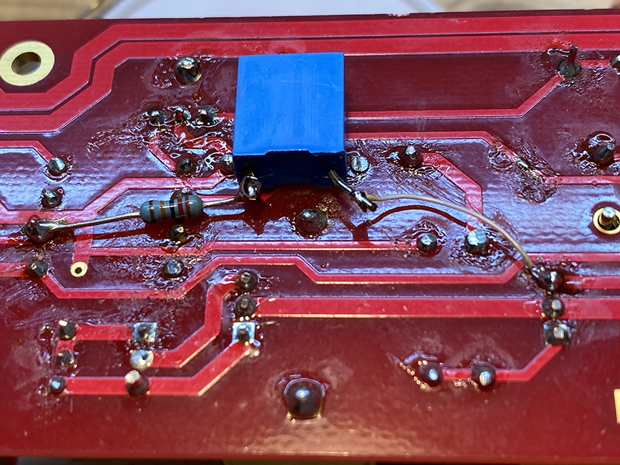
below you see the PCB i made. this PCB does have a fb pad to the cathode resistor. but it does not have a connection to the grid. there is a grid stopper on the board which i removed and replaced with 10K. i also had to edit the board a bit to squeeze in the miller compensation cap (10pF), and the trace cutting and rewiring to get “best pentode” happening.
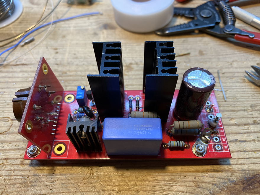
i soldered a 220K resistor to the grid pad, a 0.22uF cap to that, and the other end to the output trace. feedback loop is local and finished! i used “crazy glue” to permanently attach the cap to the pcb.
i hook up the 6.3 Volt heater supply, the regulated 270. there is actually another MOS smoother on this board that takes things from 270 to 250 Volts. that’s the closer heatsink…
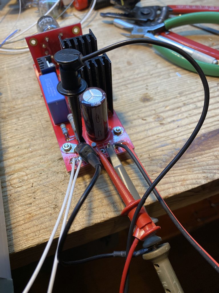
i have the scope probes connected to the output. and the signal from the generator to the input.

here you see my test setup… a homemade power supply, scope, generator… i’m keeping it basic. for those of you who are unfamiliar with using an oscilloscope in “X/Y” mode, here is an introduction. it is a basic measurement approach for me. yes, i have an audio precision on my bench. but i didn’t always have it. these tools you see are all you need to do excellent work. it was all i had for years!
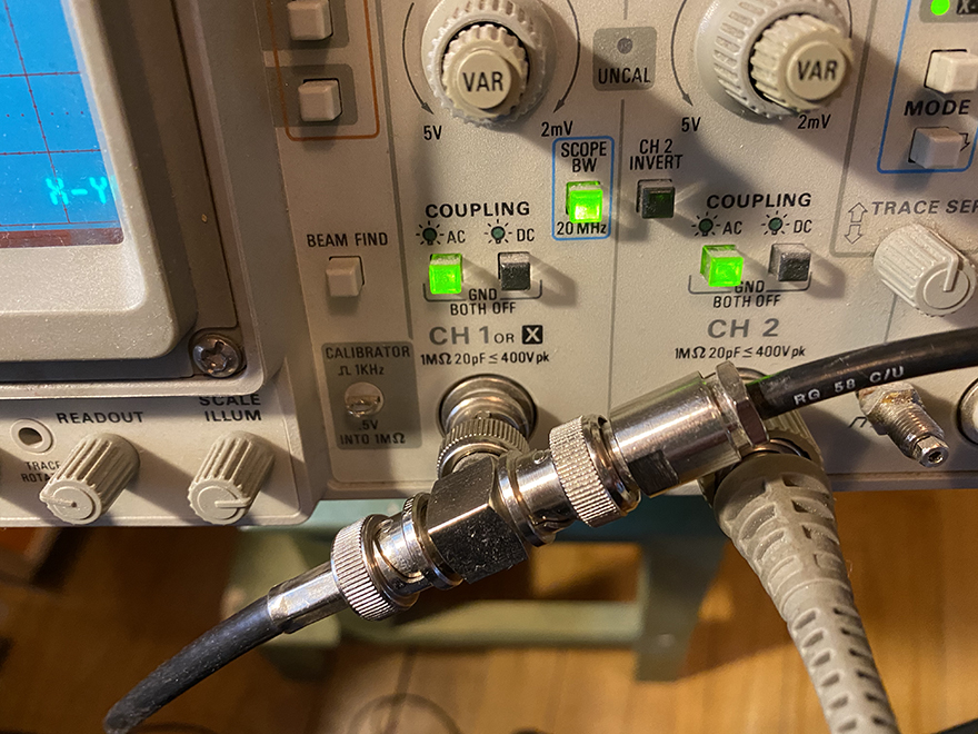
here is the arrangement for making X/Y measurements. note the generator signal comes in to CH1 (or X), and then continues to the device under test. note the scope probe is plugged into CH2 (or Y). i always use a 10X probe, unless i absolutely must have the measurement direct.
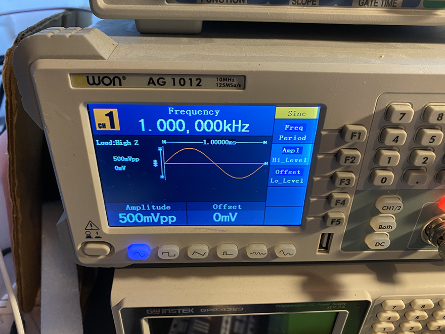
here is my generator. the screen says it all.
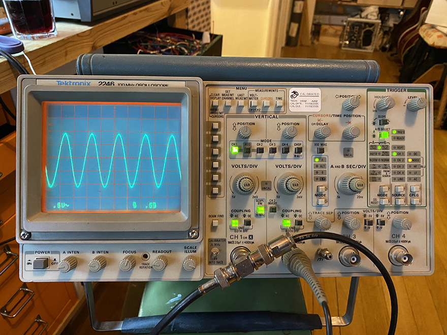
here is the signal from the generator in CH1. you can see the green indicator on CH1 below the “position” knob.
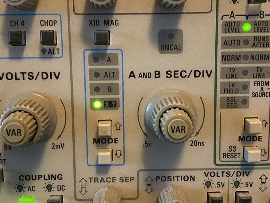
here you can select “X/Y”.. Tek scopes make it easy.
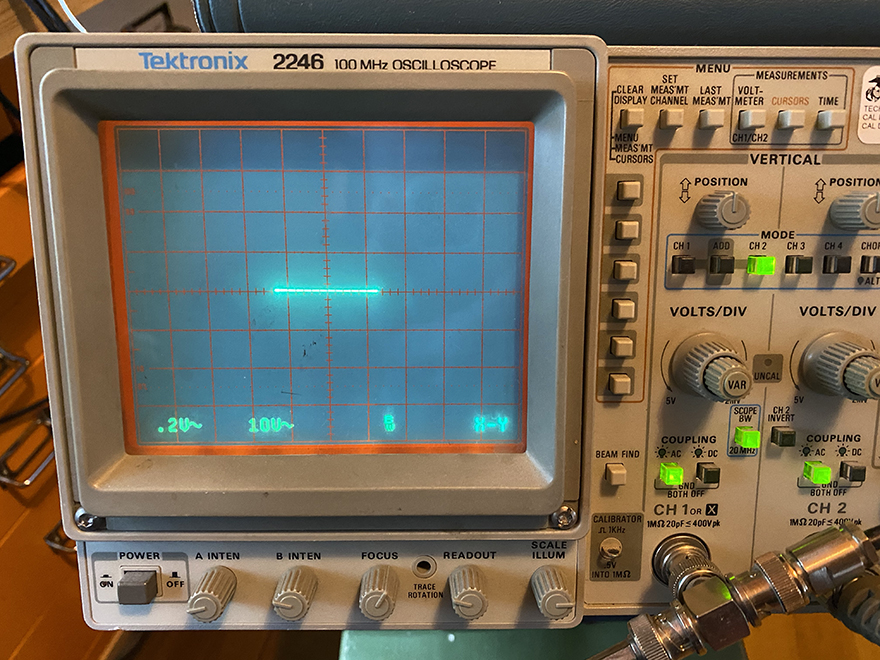
now i have switched over to CH2 and you see the 0.5 Vpp trace on the X axis. there is no output from the device under test yet… this is only the input from the generator, and it measures two and a half centimeters long. at 0.2 Volts per cm, you see 0.5 Vpp.
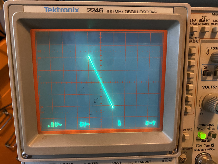
now you see the Y plotted against the X. what does this tell us? the slope of the line shows 1 Vpp at 0.5 volts pp per centimeter (the scale is sadly arranged in the metric system), and roughly 21 Volts pp of output (at 5 Volts per cm). the scope tells you how many volts per “box” right at the bottom left hand corner. the X axis is 0.5 Volts, and the Y axis is 5 Volts. we now have a “transfer characteristic” for this device. note the line is straight, without much, if any, curvature (i happen to know this is 0.06% THD, from my Audio Precision, but i am guessing not everyone has one…). the important thing is that you can know this just by looking at it! i don’t know the exact numbers of deviation, but if it’s straight like this i actually don’t NEED to know exactly! if it looks “linear” and the slope is to the LEFT, this indicates low distortion and an inverting output. if the slope of the line was to the right, but otherwise all the same, it would be non-inverting. if it was curved, like a banana, we would know that one half phase is bigger than the other… second order distortion (2nd harmonic). and if it had an “S” like curve, it would indicate 3rd order deviation. and S with a big side and a small side is both 2nd and 3rd order deviation… etc. i will make some examples and add that as an addendum, later.
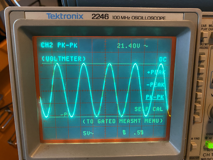
here the scope is switched to look at the sine output only…. with the waveform centered there is very little deviation. the X/Y plot is actually less ambiguous to read. it could be hard to see 5% or 10% 2nd harmonic in a sine wave, because “where is center”? but this is simple in an X/Y plot.
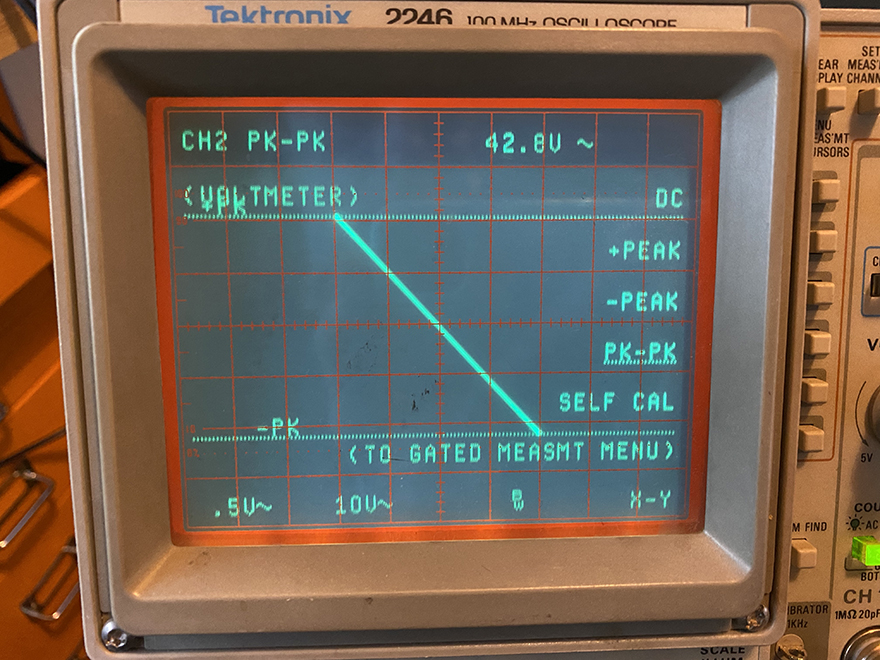
above, i have increased the input to 2 Volts pp. at 0.5 Volts per cm, “4 boxes” along the X axis… and the output is a bit more than 4 boxes of 10 Volts per cm: 42,8 Volts pp, says Tektronix… and it’s crazy straight! it’s linear to the point of boredom, i would say. not much else happening here.
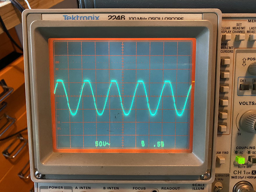
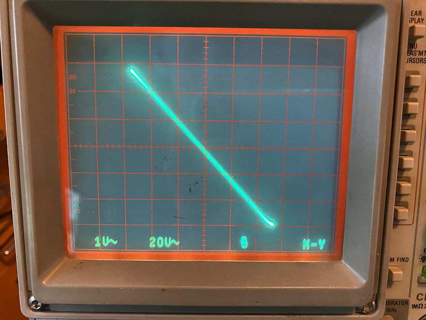
above i have deliberately overloaded the circuit. you can see hard clipping at the top, and a sharp eye might catch soft clipping at the bottom. plus a glitch down the falling edge. it’s crapping out. what does soft clipping look like in X/Y? look below… much easier to see it. i backed off of the obvious top clipping, but you can still clearly see a little hook to the right at the bottom right corner. you may also see some gentle curvature in the line too? i do.
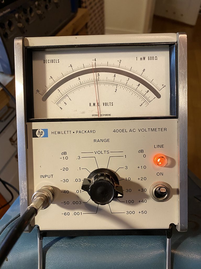
below you see i have hooked up a (GASP!) analog RMS Voltmeter. the 400 series HP meters are rightfully legendary. it’s great kit i trust more than an all but the most absurd high speed digital meters. these meters measure RMS voltage by measuring the temperature of a resistor connected to the output of a signal with a known temperature coefficient. not by comparing samples with a reference.
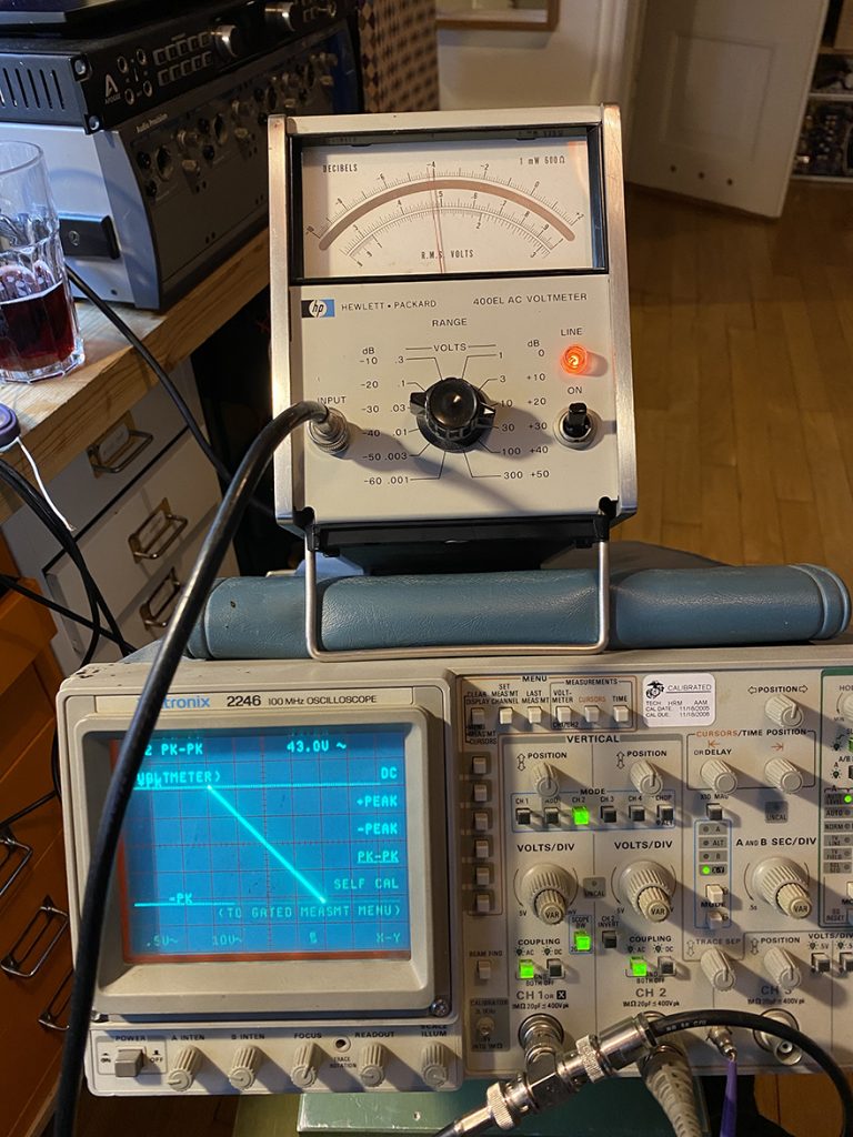
below i read 15.2 VRMS, or 42.99 Vpp
i hope this was useful. measuring gear is super important… it’s how you find out the connections between design decisions and the sound. a generator, scope and AC voltmeter are all you need, really. the curve tracer is trully lux… ha! but to see the connections between the measurements and components is what this is all about.